I was using an oscilloscope to do a little troubleshooting on a project that involved having a microcontroller flip a relay and I stumbled across something interesting. I was graphing the voltage across the relay contacts (there was a good reason for this !) and I spotted this:-
When the relay snaps shut the voltage is supposed to suddenly drop to 0 as the contacts short. As you can see that's not exactly what happened. Instead it bounces between open and shut 4 times before finally settling on closed. This all happens over 16ms so you might never know about it if you weren't looking at it on an oscilloscope. I figure what is happening here is that the moving relay contact is quite literally bouncing off the fixed one. Note how the closed period (0v) of each successive bounce becomes longer until it finally settles.
Tuesday 9 October 2012
Monday 6 August 2012
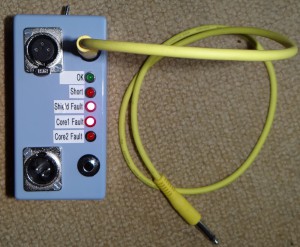
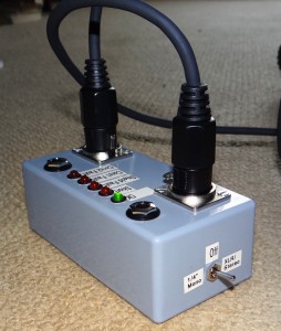
Arduino-based Audio Cable Tester
I love the Arduino platform - it makes it so quick and easy to get things done.
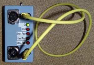
The local music school had a need to test a bunch of audio cables (1/4" and XLR) in a hurry in preparation for the annual students' concert. Yes, it can be done with a multimeter but if you have lots of them to do this becomes very tedious very quickly. Sounds like a job for an Arduino
It does XLRs also...
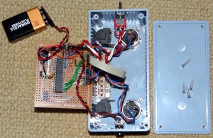
The work is all done by an Atmel Atmega mircocontroller
All of the development work is done in the Arduino environment. Once it was all working I just transferred the microcontroller onto a piece of perfboard (so that I could reuse the Arduino board for my next project). The connectors on the far-left of the board (connected to pins 1,2,3,7 and 8 ) allow the Arduino board to be used as a programmer (see http://arduino.cc/en/Tutorial/ArduinoToBreadboard). That link explains how to configure the Arduino to use the built-in 8MHz RC clock in the Atmega so no external crystal is required (neither accuracy nor flat-out CPU speed are remotely important in this application).
I also stuck a normal ICSP connector on it so that it can be programmed using a normal programmer (bottom-left corner). This is handy: once the code was complete I was able to blow the Arduino boot-loader away so that the sketch starts immediately rather than after a pause. The downside is that if I want to use an Arduino to program it again I need to reinstall the boot-loader (for which that ICSP header will be very useful !)
The source-code is posted here. The comments in the code list the required connections. I haven't bothered to draw a circuit-diagram but if anyone wants one just leave a note in the comments below and I will post it here.
Laptop Transport
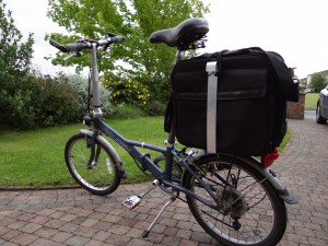
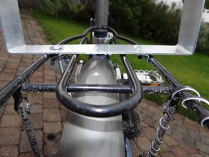
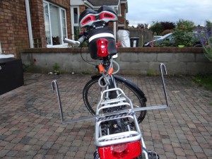
I needed a better way to carry my laptop on my folding bike. I used a backpack for a long time which works fine except on hot days (sweaty-back syndrome !). I tried a handlebar mount (the excellent but expensive Klickfix system) which also works well but it adversely affects the stability of a bike which is already a little on the twitchy side. The bike has a carrier but it is so low down that my heel clips anything that overhangs its perimeter. There had to be a better way.
My simple solution is to make an attachment for the carrier which will allow the laptop case to be mounted vertically without moving around.
The band around the laptop back is a strip of 40mm x 2mm aluminium which is attached to carrier
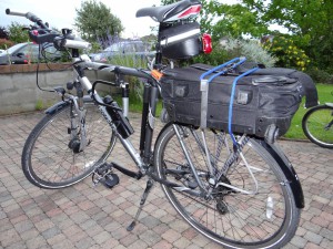
It works so well I did the same thing for the folding bike's big brother...
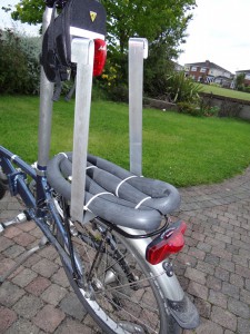
I worry a little about the laptop having the guts shaken out of it (its a very nice laptop !) so I use a folded-up and partially inflated tube to give it a little "suspension":
I hope someone finds this useful. If you have thought of a better way to solve the same problem I'd love to hear from you.
Wednesday 25 April 2012
The Sound of Music
Oscilloscopes and guitars are a wonderful combination :-)
This is what an open-E played on the 6th string of my Stratocaster knock-off looks like:-
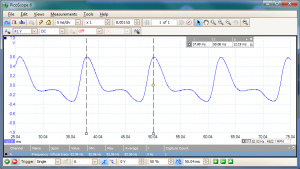
The two vertical dashed lines measure that time between two consecutive peaks (12.19ms) and from this we can work out that the fundamental frequency is 82Hz (as it should be...E on the 6th string is supposed to be 82.4Hz).
The scope can also do spectrum analysis (showing the harmonic content). Here's the same open-6th string:-
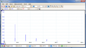
Unsurprisingly, you see a strong peak at 82.4Hz (the fundamental) with 1st harmonic (164Hz, one octave above), 2nd (247Hz, which is B on the 2nd string, nicely illustrating the relationship to the 5th note in a chord) and 3rd (329Hz, which is the E on the 1st string, two octaves above the fundamental) all strongly present. Although there isn't much of it, 4th harmonic occurs at 412Hz (you can just barely see it). This is G# played on the 1st string which illustrates the role of the major 3rd note in a chord. I think its interesting to see how the notes of a major chord all occur as harmonics of the fundamental.
Another interesting thing to look at is how tuning using harmonics works. This is the 6th string with me barely touching the string just above the 12th fret to damp the first harmonic:-
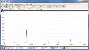
Two interesting things: the strongest peak is at 164Hz (one octave above that open E, just as you would expect). The fundamental frequency of that string is almost completely gone (because my finger prevents the string from moving at its centre point). Also, there is very little other harmonic content. Sure enough, if I graph the signal it is much closer to being a pure sine wave at 164Hz:-
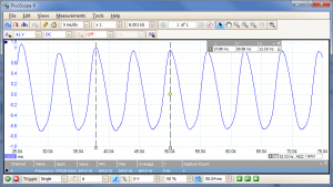
If you play that with another (nearly) pure sine wave which is only slightly different (i.e. fractionally out of tune) they will interfere with each other, creating that "fading in and out" effect that we listen for when tuning using harmonics. They will fade in and out at a rate equal to the frequency difference (which is why you can only hear it when you are very close...tuned to within a few Hz)
These graphs illustrate this pretty well. Here are harmonics on two strings (6th string 5th fret and 5th string 7th fret) which are slightly out of tune:-
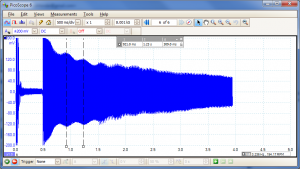
The "waviness" in the signal shows the interference between the two (at ~3Hz, measured with the vertical dashed lines) which I can hear as the characteristic fading in and out. When I correct the tuning and repeat the test...
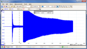
...the "waviness" is gone. This video illustrates what is going on:-
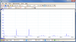
Finally, it is interesting to see the harmonic content of the same note played on two different strings. Here's the open 5th:-
And here's the same A played on the 5th fret of the 6th string:-
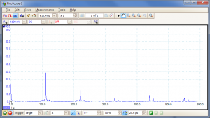
Note the much stronger fundamental (110Hz) compared to the 1st harmonic.
Saorview on the cheap
Irish readers who aren't living under a rock should know by now that the analogue terrestrial TV service will be switched off in October of this year (i.e. 2012). If you haven't make some arrangements to receive digital TV by then you will be enjoying uninterrupted views of cosmic noise, left over from the big bang (otherwise known as "snow" or "static").
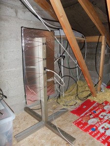
I came across plans for a homebrew antenna atwww.tvantennaplans.com (May 2019 update: the site seems to be gone, but a search for "db4 antenna plans" throws up plenty of good results). I just had to tried it and it worked beyond my wildest expectations. Here it is, mounted in my attic, facing roughly in the direction of the Kippure transmitter:-
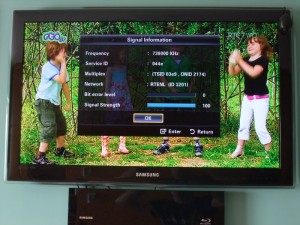
Signal strength...100%, bit-error rate...0%:-
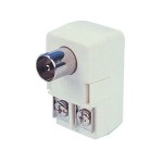
The only part I had to buy was the 300Ω <-> 75Ω balun (part number FD78K from Maplin, about €3.50)
I have been running with this for over a year now and it works perfectly. I have made a few more of them for family and friends with equal success, even in locations where analogue RTE service was poor.
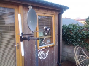
If you really really can't pick up the Saorview terrestrial service, there is also the Saorsat satellite service. You will need a Ka-band LNB (which is different to the normal type of LNB you would use for picking up Sky/Freesat etc. from Astra 2) and a dish aligned on 9oE. I tried it with an ordinary cheap-and-cheerful satellite receiver and a dinky 40cm dish mounted in a bicycle-repair stand...
...and it works a treat. You don't get TV3 or 3e at the moment but hopefully that will change. I haven't tried it, but I understand that it is possible to use a slightly bigger dish and mount a normal LNB off-centre and you can pick up both Saorsat and Sky/Freesat etc. using a single dish. www.tvtrade.ie (where I bought the Ka-band LNB among other goodies) sell a mounting bracket sized for exactly this purpose (the positioning of the LNB is critical for this trick to work). Its a great site with a great range of well-priced products. They also make their own excellent tutorial videos. Highly recommended.
I came across plans for a homebrew antenna at
Signal strength...100%, bit-error rate...0%:-
The only part I had to buy was the 300Ω <-> 75Ω balun (part number FD78K from Maplin, about €3.50)
I have been running with this for over a year now and it works perfectly. I have made a few more of them for family and friends with equal success, even in locations where analogue RTE service was poor.
If you really really can't pick up the Saorview terrestrial service, there is also the Saorsat satellite service. You will need a Ka-band LNB (which is different to the normal type of LNB you would use for picking up Sky/Freesat etc. from Astra 2) and a dish aligned on 9oE. I tried it with an ordinary cheap-and-cheerful satellite receiver and a dinky 40cm dish mounted in a bicycle-repair stand...
...and it works a treat. You don't get TV3 or 3e at the moment but hopefully that will change. I haven't tried it, but I understand that it is possible to use a slightly bigger dish and mount a normal LNB off-centre and you can pick up both Saorsat and Sky/Freesat etc. using a single dish. www.tvtrade.ie (where I bought the Ka-band LNB among other goodies) sell a mounting bracket sized for exactly this purpose (the positioning of the LNB is critical for this trick to work). Its a great site with a great range of well-priced products. They also make their own excellent tutorial videos. Highly recommended.
Subscribe to:
Posts (Atom)