Thursday 18 September 2014

Fun with Python SpiDev

I have been having a little fun trying to get a Raspberry Pi talking to a Winbond SPI W25Q80BV 1MB flash chip (PDF).   The Python SpiDev library is rather poorly documented and doesn't actually seem to do what it is supposed to do.

For starters, it offers two similar functions for transferring data over the SPI bus, called "xfer" and "xfer2".  Both take a single parameter which is a list of bytes to transfer.  According to the documentation, the difference is that for "xfer"...
"CS will be released and reactivated between blocks. delay specifies delay in µsec between blocks."
and for "xfer2"...
"Perform SPI transaction. CS will be held active between blocks."
Its not completely obvious what a "block" is in this context. I can only guess (and hope) that it might mean between two consecutive invocations of the "xfer2" function (I can't think of anything else useful that it could mean). Also, the reference to "delay" in the description of "xfer" is the only reference to a parameter, attribute or anything else called "delay" anywhere in the documentation.

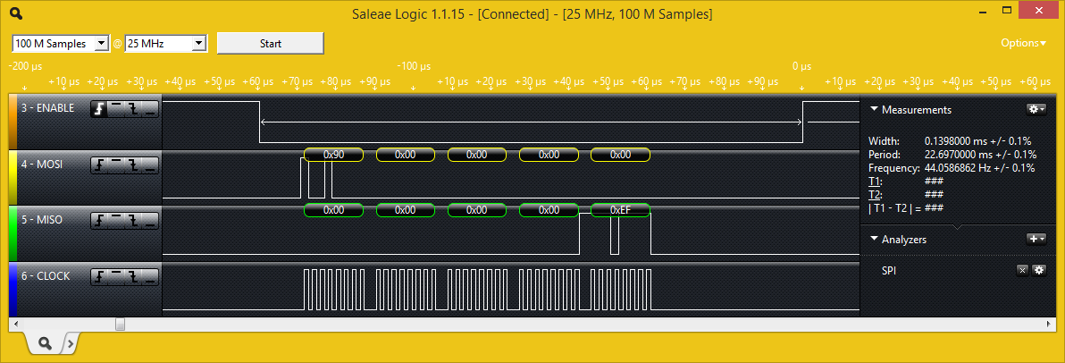
Anyway, no matter how much I tried, I couldn't see any difference between the behaviour of "xfer" and "xfer2".  Time to break out the logic analyser.  Looking at two successive calls to "xfer"...

root@alarmpi:~# python
Python 2.7.3 (default, Mar 18 2014, 05:13:23) 
[GCC 4.6.3] on linux2
Type "help", "copyright", "credits" or "license" for more information.
>>> import spidev
>>> 
>>> spi = spidev.SpiDev()
>>> spi.open(0,0)
>>> 
>>> spi.xfer([0x90,0,0,0,0])
[0, 0, 0, 0, 239]
>>> spi.xfer([0x90,0,0,0,0])
[0, 0, 0, 0, 239]

I pasted the commands in, so the two calls to "spi.xfer" happened very close together in time.


As you would expect, the ENABLE (a.k.a. /CS) line goes low at the beginning of each transfer and high again as soon as the transfer completes.  No problems there...that's what the documentation says is supposed to happen.  Here's what one of the transactions looks like close up:-


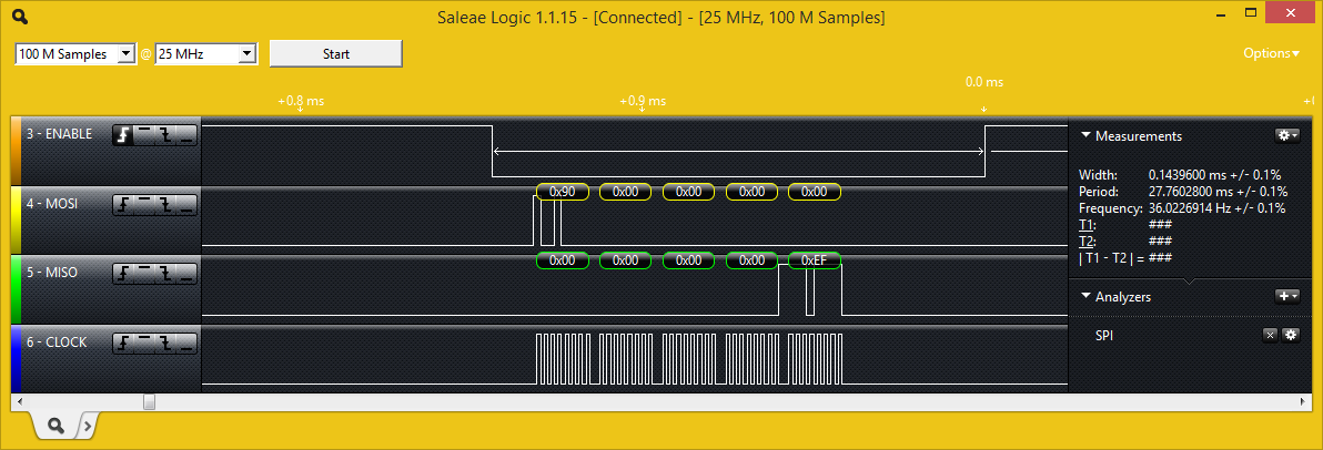
Now to try the same test using "xfer2" instead of "xfer".  As I interpret the documentation, the /CS line should stay low between transfers, so that two consecutive calls to "xfer2" would actually look like a single SPI bus transaction, albeit with a bit of a hiatus in the middle.  However, that is not what happens.


If there's a difference there, I'm not seeing it.


Apparently I'm not the first one to ponder this mystery: here and here.

Which brings me to the mysterious "delay" parameter.  It turns out that the "xfer" and "xfer2" functions both take three additional parameters (determined by studying the SpiDev source code).

spi.xfer([values], speed_hz, delay_usecs, bits_per_word)

You can set "speed_hz" to 0 and it will default to the maximum supported speed.  "delay_usecs" goes into a 16-bit unsigned integer, so it looks like the longest you can stretch the /CS hold delay by is 65.5ms.  Worth a shot:-

>>> spi.xfer2([0x90,0,0,0,0], 0, 65535)
spi.xfer2([0x90,0,0,0,0], 0, 65535)
[0, 0, 0, 0, 239]
>>> spi.xfer2([0x90,0,0,0,0], 0, 65535)
[0, 0, 0, 0, 239]


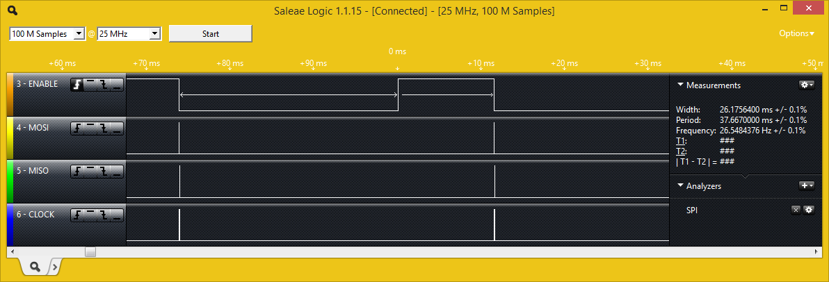
It definitely did something: /CS now stays low for 26ms after the transaction is complete.  Its not the 65.5ms we were expecting, though.  

I determined experimentally that the delay used is actually modulo 40,000us.  Any value up to 40,000 works as it should...any value higher than 40,000 has 40,000 subtracted from it.  This is true whether I use "xfer" or "xfer2": I still can't find any difference in behaviour between the two.  

Returning to the SpiDev module source code, the lack of any behavioural difference between "xfer" and "xfer2" isn't surprising: it turns out that both of them actually make exactly the same IOCTL call to the SPI kernel module with a spi_ioc_transfer structure populated in exactly the same way.  That structure does actually contain a member called "cs_change" which is described as:-

@cs_change: True to deselect device before starting the next transfer
...which sounds exactly like it should be the difference between "xfer" and "xfer2".  However, neither method actually sets this structure member either way.  So it looks like the value for this parameter that is passed to the kernel is what ever random value is in memory when the space for the structure is allocated. It seems like it should be easy to fix so I will try modifying the source code to correct this problem.  But not tonight...that's an update for another day.

What I really wanted to do but (apparently) can't is to read continuously from the SPI flash IC.  All I should have to do is send it a "read" command and a start address, and then just keep reading from it in one big, 1,048,576-byte long transaction and it should happily return the entire flash contents in sequence.  This works fine on an Arduino: I set up the "read" operation and then just keep feeding it values (it doesn't matter what I send...its the value that the flash IC returns that I'm interested in) with the /CS pin held low.  However, with "xfer2" not working as it should, there seems to be no way to spread a single SPI bus transaction among multiple method calls.  Even if "xfer2" did work its not ideal.  There is a "readbytes" function which would be more appropriate because it doesn't require me to send it in a list of values to transmit (which will all be ignored anyway).  However, there is no "readbytes2" (working or otherwise) which would allow the /CS to be held low between successive calls.


Friday 12 September 2014

Hakko FX888D 110V to 220V conversion

For a while now, I have fancied a Hakko FX888D soldering station. However, for some reason they are difficult to get in 220V form and - when they can be found - are shockingly more expensive than the 110V.  There seems to be no good reason for this: the only difference between the two appears to be the mains transformer.  Inspired by a YouTube video posted by egressvk, I decided to risk $100 and order a 110V version with a view to doing my own conversion.

I already had a cheap (incredibly cheap, actually) Yihua 936 soldering station which I got from Hobby King for €14.


Dave Jones at EEVBlog reviews it in his usual entertaining style here.  Its actually not bad, especially for the price, but when you put it side-by-side with the Hakko the differences are apparent.


The Hakko is heavier and feels more robust.  The heat-resistant collar is also of much higher quality. Its not apparent from just looking at a picture, but the cable on the Hakko is made from silicone rather than PVC and is much more flexible (and longer).  The stand that comes with the Hakko is also in a completely different league to the Yihua.  But so is the price and the Yihua works perfectly well so I'm not complaining.

Anyway, despite its virtues, I resolved that the Yihua was going to make the ultimate sacrifice and become a transformer donor for the FX888D conversion.  This is where I got a very pleasant surprise: it turns out that the transformer in the Yihua is a perfect fit for the Hakko.  The transformer has the same dimensions and even the mounting holes line up perfectly with the pillars in the FX888D body.  This was shaping up to be the easiest hack of all time !

Here is the Hakko with the transformer from the Yihua already fitted (but with the secondary side not wired in yet).  The original Hakko transformer is just below for comparison


I even took the original switch+fuse+mains-cable assembly from the Yihua, slotted the switch into the switch cutout in the Hakko body and secured the mains cable into the cable clamp. One minor problem with this approach is that the back of that mains switch+fuse assembly was awfully close to the body of the transformer.  To make sure they didn't touch, I slipped a bit of blank (no copper) perfboard in between the two and hot-glued it to the plastic pillars:


This is probably a little bit dodgy, if I'm honest: I may yet go back and use the power switch and fuse assembly from the Hakko transformer.  Assuming that I'm not electrocuted first, that is.

I had a little debate with myself about the best way to connect the secondary from the new transformer to the controller board.  Strip connector?   Solder+heatshrink the wires together? In the end, I desoldered the original wires (the red ones, visible in the top right-hand corner), cleaned out the holes (the most difficult part of the entire conversion !) and soldered the outputs from the new transformer directly to the board.

When I first powered up the unit after the conversion, the temperature on the display quickly shot up to 750F (just under 400C).  It seemed to me that the iron was running hotter than this and - sure enough - when I checked with a thermocouple the tip was closer to 900F.  I could compensate for this by just reducing the setpoint and the controller would hold the temperature steady, but it was a bit of a bummer to have the displayed temperature completely wrong.  I suppose I could have a faulty unit, but it was too late to submit a warranty claim now :-).  Anyway, I came across this YouTube describing how to reset the controller to its factory defaults. Without much optimism, I followed these instructions and it worked !!  The tip temperature measured with a thermocouple now (broadly) matches the temperature shown on the controller's LED display.

I'm used to thinking in degrees Celsius/Centigrade rather than in Fahrenheit which is the out-of-the-box default on the FX888D.  Thankfully, changing the display units is easy.


(these were real "wish I had a third hand" photos to take !)

This is a fantastic result: the conversion couldn't be any neater and I couldn't buy a transformer any cheaper than I got the Yihua 936 for.  As a bonus, I will reuse the (rather nice) enclosure that the Yihua controller came in for something else.

UPDATE January 2015:  I have been using this soldering iron regularly now for a few months and I couldn't be happier with it.  It is quick to heat up, holds its temperature rock-steady and it is comfortable to use.