Wednesday, 27 May 2020

40dB Stereo Pad + Balanced-to-Unbalanced

The 30/40dB pad from my previous post works fantastically well. I have been using it to bring the balanced line-level output from a mixing desk down to an acceptable level for the microphone input on my camera and the sound-quality is crystal-clear. 

But it is time for version 2.0.  The things I want to change:-
  • Stereo. Up to now, the cable I have been using to connect the pad to the camera simply connects the camera's L and R inputs together. It works fine, but the camera records two audio channels and I want to use them. 
  • The first version is nice and general-purpose: it provides balanced output, handy for feeding into a balanced microphone input, if I ever wanted to. But my camera doesn't have a balanced input, so a camera-specific version with unbalanced output to a more convenient connector (phono or 1/4" stereo) would make connecting up a little easier (although I do love how rock-solid XLR connectors are). I'm willing to sacrifice some generality for convenience here.
  • I don't really need it to have a switchable attentuation level.  The mixer has an output level fader and the camera has variable sensitivity on its microphone input. I'm willing to sacrifice the flexibility of a switchable attenuation level to reduce the (slight) risk that the contacts in the switch will become oxidised and noisy at some point.
Here is the schematic for version 2.0


The pad part is mostly the same as the earlier version.  I included some extra resistors (R1, R3, R6 and R8) that I have bridged with little wire links to give myself some flexibility.  If I want to increase the attenuation, I can snip the wire links which will increase the attenuation to around 45dB.  I had the board space (and the resistors) so it seemed a shame not to use it.  At the output, I have given myself a choice of either 1/4" stereo jack output or 2 x phonos.

If I had thought of it, I might have included a way to bypass the pad completely so that I could use this to connect two dynamic microphones (with balanced XLR outputs) directly to the camera input without any attenuation, but I didn't think of it (until now).  That's what version 3.0 is for, I guess.

This is what it looks like:-


I haven't tried it in anger yet, but initial testing is positive.  I'll report back once it has had its first proper outing.

UPDATE January 2021: I have been using this gadget regularly since May and it works absolutely perfectly: I am very happy with the result.  The amount of attenuation is applies is just about perfect and I haven't felt the need to snip the wires bypassing R1, R3, R6 and R8.  I do have about 12dB of attenuation dialed in on the camera's microphone input, bringing total attenuation up to about 42dB, which sounds about right and - more importantly - lands the recorded audio levels just about where I want them.

Tuesday, 21 April 2020

30dB/40dB Switchable Balanced Pad

I had a requirement to connect the (line-level) output from a small mixing desk into the microphone input on my camera (mic-level, obviously). I was using a DI box with a 30dB pad in it, but that required a 9V battery which was sure to run out at the most inopportune moment.  Since the camera didn't take balanced input anyway, there was no real need for the DI (in fact, the cable from the DI into the camera was wired as a balanced-to-unbalanced cable).  A little bit of internet research led me to http://www.uneeda-audio.com/pads/ which has all of the relevant information (but does require careful study !).  Based on that, here's what I came up with:-


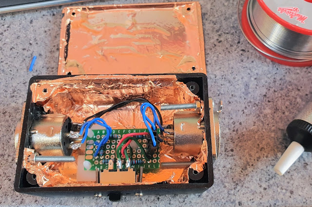
This gives me the option of either 30dB or 40dB of attenuation, depending on the position of the switch (I find that with the in-camera gain turned down as far as it will go, 30dB is enough, but the flexibility is nice to have).  The input impedance seen by the mixer is about 27K at 40dB and about 6.8K at 30dB.  The output impedance presented to the camera is 220Ω.  It works pretty well.  I built it into a small plastic project box lined with copper foil (originally bought with the intention of shielding a guitar cavity):-


The resistors are of the metal film type to minimise thermal noise.

This is the end-result:-


It is fairly compact and rugged, completely noiseless and doesn't require any power.  

The justification for the choice of resistor values is as follows.  The general equation for gain (which will be negative) of a resistor divider network is:-
...where Ris the lower resistor in the circuit diagram and Ris the sum of the resistors labelled R1.n in the circuit diagram above.  So, for 30dB of attenuation, the switch is closed and the 10K resistors are bypassed and the equation becomes:-
With the switch open, the 10K resistors are included in series and the equation becomes:-


I could (possibly should?) have used a slightly lower resistor value than 10K to land a little closer to -40dB.  7.5K would have done it, but it had already been a long night.  a 30K resistor in parallel with each of the 10Ks would do the trick.