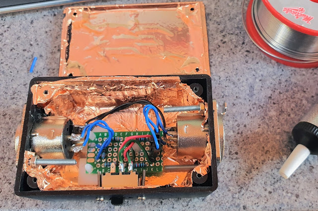
This gives me the option of either 30dB or 40dB of attenuation, depending on the position of the switch (I find that with the in-camera gain turned down as far as it will go, 30dB is enough, but the flexibility is nice to have). The input impedance seen by the mixer is about 27K at 40dB and about 6.8K at 30dB. The output impedance presented to the camera is 220Ω. It works pretty well. I built it into a small plastic project box lined with copper foil (originally bought with the intention of shielding a guitar cavity):-
The resistors are of the metal film type to minimise thermal noise.
This is the end-result:-
It is fairly compact and rugged, completely noiseless and doesn't require any power.
The justification for the choice of resistor values is as follows. The general equation for gain (which will be negative) of a resistor divider network is:-
...where R2 is the lower resistor in the circuit diagram and R1 is the sum of the resistors labelled R1.n in the circuit diagram above. So, for 30dB of attenuation, the switch is closed and the 10K resistors are bypassed and the equation becomes:-
With the switch open, the 10K resistors are included in series and the equation becomes:-I could (possibly should?) have used a slightly lower resistor value than 10K to land a little closer to -40dB. 7.5K would have done it, but it had already been a long night. a 30K resistor in parallel with each of the 10Ks would do the trick.


No comments:
Post a Comment