For starters, it offers two similar functions for transferring data over the SPI bus, called "xfer" and "xfer2". Both take a single parameter which is a list of bytes to transfer. According to the documentation, the difference is that for "xfer"...
"CS will be released and reactivated between blocks. delay specifies delay in µsec between blocks."
and for "xfer2"...
"Perform SPI transaction. CS will be held active between blocks."Its not completely obvious what a "block" is in this context. I can only guess (and hope) that it might mean between two consecutive invocations of the "xfer2" function (I can't think of anything else useful that it could mean). Also, the reference to "delay" in the description of "xfer" is the only reference to a parameter, attribute or anything else called "delay" anywhere in the documentation.
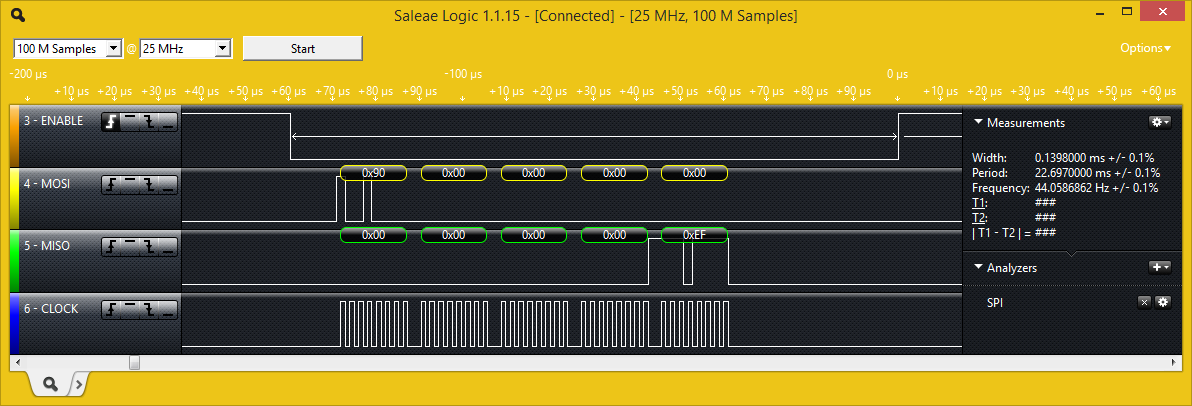
Anyway, no matter how much I tried, I couldn't see any difference between the behaviour of "xfer" and "xfer2". Time to break out the logic analyser. Looking at two successive calls to "xfer"...
root@alarmpi:~# python
Python 2.7.3 (default, Mar 18 2014, 05:13:23)
[GCC 4.6.3] on linux2
Type "help", "copyright", "credits" or "license" for more information.
>>> import spidev
>>>
>>> spi = spidev.SpiDev()
>>> spi.open(0,0)
>>>
>>> spi.xfer([0x90,0,0,0,0])
[0, 0, 0, 0, 239]
>>> spi.xfer([0x90,0,0,0,0])
[0, 0, 0, 0, 239]
I pasted the commands in, so the two calls to "spi.xfer" happened very close together in time.

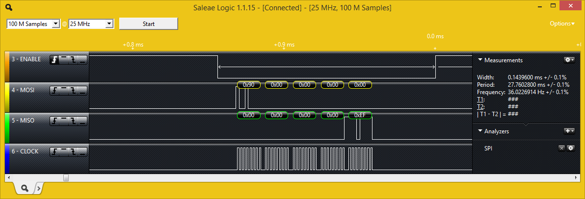
Now to try the same test using "xfer2" instead of "xfer". As I interpret the documentation, the /CS line should stay low between transfers, so that two consecutive calls to "xfer2" would actually look like a single SPI bus transaction, albeit with a bit of a hiatus in the middle. However, that is not what happens.

Which brings me to the mysterious "delay" parameter. It turns out that the "xfer" and "xfer2" functions both take three additional parameters (determined by studying the SpiDev source code).
spi.xfer([values], speed_hz, delay_usecs, bits_per_word)
You can set "speed_hz" to 0 and it will default to the maximum supported speed. "delay_usecs" goes into a 16-bit unsigned integer, so it looks like the longest you can stretch the /CS hold delay by is 65.5ms. Worth a shot:-
>>> spi.xfer2([0x90,0,0,0,0], 0, 65535)
spi.xfer2([0x90,0,0,0,0], 0, 65535)
[0, 0, 0, 0, 239]
>>> spi.xfer2([0x90,0,0,0,0], 0, 65535)
[0, 0, 0, 0, 239]
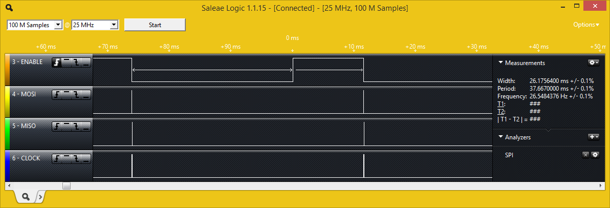
It definitely did something: /CS now stays low for 26ms after the transaction is complete. Its not the 65.5ms we were expecting, though.
I determined experimentally that the delay used is actually modulo 40,000us. Any value up to 40,000 works as it should...any value higher than 40,000 has 40,000 subtracted from it. This is true whether I use "xfer" or "xfer2": I still can't find any difference in behaviour between the two.
Returning to the SpiDev module source code, the lack of any behavioural difference between "xfer" and "xfer2" isn't surprising: it turns out that both of them actually make exactly the same IOCTL call to the SPI kernel module with a spi_ioc_transfer structure populated in exactly the same way. That structure does actually contain a member called "cs_change" which is described as:-
@cs_change: True to deselect device before starting the next transfer...which sounds exactly like it should be the difference between "xfer" and "xfer2". However, neither method actually sets this structure member either way. So it looks like the value for this parameter that is passed to the kernel is what ever random value is in memory when the space for the structure is allocated. It seems like it should be easy to fix so I will try modifying the source code to correct this problem. But not tonight...that's an update for another day.
What I really wanted to do but (apparently) can't is to read continuously from the SPI flash IC. All I should have to do is send it a "read" command and a start address, and then just keep reading from it in one big, 1,048,576-byte long transaction and it should happily return the entire flash contents in sequence. This works fine on an Arduino: I set up the "read" operation and then just keep feeding it values (it doesn't matter what I send...its the value that the flash IC returns that I'm interested in) with the /CS pin held low. However, with "xfer2" not working as it should, there seems to be no way to spread a single SPI bus transaction among multiple method calls. Even if "xfer2" did work its not ideal. There is a "readbytes" function which would be more appropriate because it doesn't require me to send it in a list of values to transmit (which will all be ignored anyway). However, there is no "readbytes2" (working or otherwise) which would allow the /CS to be held low between successive calls.
Excellent!!!! You nailed it. You are a high quality expert! Thx.
ReplyDeleteIs there a difference between spidev (3.2) and the library 'python-periphery', or the 'py-libbcm2835' library? They all seem to do spi, however not sure if they have different applications or if they are just deprecated libraries?
ReplyDeleteInterestingly, the spidev documentation says you can set the number of bits per word(transfer) , 8..16, however according to the pi documentation, the spi peripheral connected to the header only supports 8/9! So perhaps spidev is a generic driver whose functionality may or may not be fully supported by the rpi?
BTW, doesn't a python list ([0x90,0,0,0,0]) consist of ints and not bytes? Does the driver take this into account and convert it to bytes before sending?
I just ran into the same problem (except I want one big write of 256kB).. But have a work-around.
ReplyDeleteInstead of using CE0, connect CS on the slave to a GPIO. Then:
- assert GPIO low (chip enable)
- do your transactions 4096B at a time
- assert your GPIO high (chip disable)
works a treat!
#Note this has been modified to maually assert CS on data line and
#then send multiple blocks of data until complete
def send_block(data, p_cs):
max_block_size = 4096 #Limitation in spidev and xfer2 doesn't work!
data_remaining_size = len(data)
GPIO.output(p_cs, GPIO.LOW)
time.sleep(0.000001) #1us for CS to properly assert
while data_remaining_size > 0:
this_block = data[:max_block_size]
#print this_block
spi.xfer(this_block)
del data[:max_block_size]
data_remaining_size = len(data)
GPIO.output(p_cs, GPIO.HIGH)
Thanks for the workaround, Edward. I'm kicking myself that I didn't think of it: a lesson on how easy it is to get stuck thinking about a problem just one way - something I generally try to do my best to avoid. I think I still have that flash IC somewhere in the parts bin...I'll have to dig it out and try your workaround (although I can't see any reason why it shouldn't work.
DeleteNo probs! But thank you for a well written and informative post that convinced me that I was banging my head against a wall with xfer2() in the first place.
ReplyDeleteIt's useful gems like this (blog) and google search that saves valuable engineering time.
Hi everyone
ReplyDeleteI'm trying to 24 bits data send between Pi and ad5422 using spi throw spiDev in python .The input shift register is 24 bits wide. Data is loaded into the device MSB first as a 24-bit word under the control of a serial clock input, SCLK. Data is clocked in on the rising edge of SCLK. The input register consists of eight address bits and 16 data bits. The 24-bit word is unconditionally latched on the rising edge of the LATCH pin. foe example send data: address 0x01 , data:0x0148 =>0x010148 Does anyone know what am I doing? my code is:
import spidev
import time
import RPi.GPIO as GPIO # import RPi.GPIO module
from time import sleep # lets us have a delay
GPIO.setmode(GPIO.BCM) # choose BCM or BOARD
GPIO.setup(12, GPIO.OUT) # set GPIO24 as an output
spi_bus = 3
spi_device = 0
spi = spidev.SpiDev()
spi.open(spi_bus, spi_device)
spi.max_speed_hz = 1000000
send_controll=0x55
send_data_ctrl1=0xb0
send_data_ctrl2=0x06
send_add=0x01
send_data=0x01
send_data=0x48
try:
print("set GIOP high")
#spi.xfer2([send_controll])
spi.xfer2([send_controll,send_data_ctrl,send_data_ctrl2])
GPIO.output(12, 1)
sleep(0.01)
GPIO.output(12, 0)
sleep(0.5)
spi.xfer2([send_add,send_data1,send_data2])
GPIO.output(12, 1)
sleep(0.01)
GPIO.output(12, 0)
print("end GIOP high")
except KeyboardInterrupt: # If CTRL+C is pressed, exit cleanly:
print("Keyboard interrupt")
except:
print("some error")
finally:
print("clean up")
GPIO.cleanup() # cleanup all GPIO
but it didn't work.
Hi! Is there any way I can get multiple values using xfer rather than one value at a time. In the list parameter for xfer, I passed in the same values multiple times that I initially used to get just one value. However, I get the first value right and the rest of them are just zeros.
ReplyDelete